IPML: Structuring distributed multimedia presentations in Ambient Intelligent Environments
Department of Industrial Design
Eindhoven University of Technology
5600MB Eindhoven, The Netherlands
Abstract This paper addresses issues of distributing multimedia presentations in an ambient intelligent environment, examines the existing technologies and proposes IPML, a markup language that extends SMIL for distributed settings. It uses a metaphor of play, with which the timing and mapping issues in distributed presentations are covered in a natural way. A generic architecture for playback systems is also presented, which covers the timing and mapping issues of presenting an IPML script in heterogeneous ambient intelligent environments.
Keywords: Distributed Multimedia, Software Architecture, Ambient Intelligence, Play
INTRODUCTION
Ambient Intelligence (AmI) is introduced by Philips Research as a new paradigm in how people interact with technology. It envisions digital environments to be sensitive, adaptive, and responsive to the presence of people, and AmI environments to change the way people use multimedia services (Aarts, 2004). The environments, which include many devices, will play interactive multimedia to engage people in a more immersive experience than just watching television shows. People will interact not only with the environment itself, but also with the interactive multimedia through the environment.
For many years, the research and development of multimedia technologies have increasingly focused on models for distributed applications, but the focus was mainly on the distribution of the media sources. Within the context of AmI, not only are the media sources distributed, the presentation of and the interaction with the media will also be distributed across interface devices. This paper focuses on the design of the structure of multimedia content, believing that the user experience of multimedia in a distributed environment can be enriched by structuring both the media content at the production side and the playback system architecture at the user side in a proper way. We refer to the adaptation at the user side as the mapping problem. One important aspect of the mapping problem is sketched in Figure 1. The content source and the script should be independent from the question which specific devices are available at the user’s side. This may vary from a sophisticated home theater with interactive robots (left) to a simple family home with a television-like device and a lamp (right). There is no a priori limit to the type of devices, for example PDAs and controllable lights are possible as well. The playback environment need not even be a home; it could be a professional theater or a dedicated installation. The structure should enable both the media presentation and the user interaction to be distributed and synchronized over the networked devices in the user environment. The presentation and interaction should be adaptive to the profiles and preferences of the users, and the dynamic configurations of the environment.
As El-Nasr and Vasilakos (2006) point out, there is very little work that allows the adaptation of the real environment configuration to the cognitive spaces of the artists, in our example, the authors of the content and the script. The area of Cognitive Informatics (Wang, 2006, 2007) provides interesting insights into this issue. In particular this is a field studies the mechanisms and process of natural processing and intelligence, including emotions, cognition, decision making, and its application to entertainment, engineering, educational, and other applications. On the one hand, the users and the authors should not be bothered by the complexity hidden behind the surface of the ambient intelligence; on the other hand the ambient intelligent environment should be able to interpret the user’s needs in interaction and to adapt to the author’s requirements in presentation. The common part that the users and the authors share is not a particular user’s environment, but only the media content. The media content should be structured in such a way, that the requirements from the both sides can meet. To structure the media content, the following issues need to be addressed:
1. By what means will the authors compose the content for many different environments? The authors have to be able to specify the following with minimized knowledge of the environments: (a) Desired environment configurations; (b) Interactive content specification for this environment.
2. How can the system play the interactive media with the cooperation of the user(s) in a way that: (a) makes the best use of the physical environment to match the desired environment on the fly; (b) enables context dependent presentation and interaction. Here the term “context” means the environment configuration, the application context, the user preferences, and other presentation circumstances; (c) synchronizes the media and interaction in the environment according to the script.
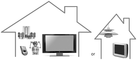
Figure 1. The mapping problem caused by variations in playback system architecture
This paper first examines existing open standards for synchronized media. Then the notion of “play” is introduced as a unifying concept, first in an informal way, later formalized through the design of the language. The language is developed in two steps: first an existing scripting language and then the language IPML which takes full advantage of the notion of play and addresses all of the aforementioned issues. The latter language is based on a generic architecture for the playback system that covers the timing and mapping problems.
Then we discuss the three main architectural design elements which are needed to bring the plays, written in this language, to live: distributed agents, an action synchronization engine, and an IPML mapper. It is through this design that we validate the concepts and thus prove the feasibility of IPML and demonstrate its value.
OPEN STANDARDS FOR SYNCHROIZED MEDIA
SMIL and MPEG-4 are contemporary technologies in the area of synchronized multimedia (Battista, Casalino, & Lande, 1999, 2000). SMIL focuses on Internet applications and enables simple authoring of interactive audiovisual presentations, whereas MPEG-4 is a superset of technologies building on the proven success in digital television, interactive graphics applications and also interactive multimedia for the Web. Both were the most versatile open standards available at moment of starting the design trajectory.
But both were challenged by the requirement for distributed interactions. It requires that the technology is first of all able to describe the distribution of the interaction and the media objects over multiple devices. The BIFS in MPEG-4 emphasizes the composition of media objects on one rendering device. It doesn’t take multiple devices into account, nor does it have a notation for it.
SMIL 2.0 introduces the MultiWindowLayout module, which contains elements and attributes providing for creation and control of multiple top level windows (Rutledge, 2001). This is very promising and comes closer to the requirements of distributed content interaction. Although these top level windows are supposed to be on the same rendering device, they can to some extent, be recognized as software interface components which have the same capability.
To enable multimedia presentations over multiple interface devices, StoryML was proposed (Hu, 2003). It models the interactive media presentation as an interactive Story presented in a desired environment (called a Theater). The story consists of several Storylines and a definition of the possible user Interaction during the story. User interaction can result in switching between storylines, or changes within a storyline. Dialogues make up the interaction. A dialogue is a linear conversation between the system and the user, which in turn consists of Feed-forward objects, and the Feedback objects that depend on the user’s response. The environment may have several Interactors. The interactors render the media objects. And finally, the story is rendered in a Theater.
One problem of StoryML is that it uses a mixed set of terms. “Story” and “storylines” are from narratives, “media objects” are from computer science, whereas interactors are from human computer interaction. Scripting an interactive story requires various types of background knowledge. It is questionable whether StoryML has succeeded in both keeping the scripting language at a high level and let the script authors only focus on the interactive content. “Movies did not flourish until the engineers lost control to artists – or more precisely, to the communications craftsmen.” (Heckel, 1991)
StoryML uses storytelling as a metaphor for weaving the interactive media objects together to present the content as an “interactive story”. This metaphor made it difficult to apply StoryML to other applications when there are no explicit storylines or narratives. Moreover, StoryML can only deal with linear structure and use only a storyline switching mechanism for interaction.
Reflecting on our experiences with StoryML, it is necessary to design a script language that has a more generic metaphor, that supports both linear and nonlinear structures and that can deal with complex synchronization and interaction scenarios. Next we introduce the metaphor of “play”, for the design of the new scripting language, IPML.
PLAY
Instead of storytelling, Interactive Play Markup Language (IPML) uses the more powerful metaphor of play. A play is a common literary form, referring both to the written works of dramatists and to the complete theatrical performance of such. Plays are generally performed in a theater by actors. To better communicate a unified interpretation of the text in question, productions are usually overseen by a director, who often puts his or her own unique interpretation on the production by providing the actors and other stage people with a script. A script is a written set of directions that tell each actor what to say (lines) or do (actions) and when to say or do it (timing). If a play is to be performed by the actors without a director and a script from the director, the results are unpredictable, if not chaotic. It is not the intention of this paper to give a definitive and extensive definition of the term “play”, nor to reproduce all elements of such a rich art form. Only the necessary parts are taken for easier understanding and communication when composing a markup script. Here we use the word “play” for both its written form of a script, and the stage performance form of this script.
Timing in a Play
Timing in a play is very important whether it be when an actor delivers a specific line, or when a certain character enters or exits a scene. It is important for the playwright to take all of these into consideration. The following is an example from Alice in Wonderland (Carroll & Chorpenning, 1958):
···
ALICE: Please! Mind what you’re doing!
DUCHESS (tossing ALICE the baby): Here . . . you may nurse it if you like. I’ve got to get ready to play croquet with the Queen in the garden. (She turns at the door.) Bring in the soup. The house will be going any minute! (As the DUCHESS speaks, the house starts moving. The COOK snatches up her pot and dashes into the house.)
COOK (to the FROG): Tidy up, and catch us! (The FROG leaps about, picking up the vegetables, plate, etc.)
ALICE (as the FROG works): She said “in the garden.” Will you please tell me –
FROG: There’s no sort of use asking me. I’m not in the mood to talk about gardens.
ALICE: I must ask some one. What sort of people live around here?
···
A few roles are involved in this part of the play. Their lines and actions are presented by the playwright in a sequential manner, and these lines and actions are by default to be played in sequence. However, these sequential lines and actions are often not necessarily to happen immediately one after another. For example, it is not clear in the written play how much of time the duchess should take to perform the action “tossing Alice the baby” after Alice says “Mind what you’re doing” and before the duchess says “Here . . . you may nurse it if you like”. The director must supervise the timing of these lines and actions for the actors to ensure the performance is right in rhythm and pace. Furthermore, things may happen in parallel – For example, the house starts moving as the duchess speaks, and Alice talks as the frog works. Parallel behaviors are often described without precise timing for performing. It is up to the directors to decide the exact timing based on their interpretation of the play. For example, the director may interpret “As the DUCHESS speaks, the house starts moving” as “at the moment of the duchess start saying ‘The house will be going in any minute’, the house starts moving”.
Mapping: Assigning Roles to Actors
Actors play the roles that are described in the script. One of the important tasks of the director is to define the cast – assign the roles to actors. This is often done by studying the type of a role and the type of an actor, and finding a good match between them. This is also exactly the problem for distributed presentations: determining which device or component to present certain type of media objects. It can be very hard for a computer to carry out this task, unless these types are indicated in some way otherwise.
In some traditional art of play, these types are even formalized so that a play can be easily performed with a different cast. We found a perfect source of inspiration in Beijing Opera. The character roles in Beijing Opera are divided into four main types according to the sex, age, social status, and profession of the character: male roles (Sheng, Figure 2(a)); female roles (Dan, Figure 2(b)); the roles with painted faces (Jing, Figure 2(c)) who are usually warriors, heroes, statesmen, or even demons; and clown (Chou, Figure 2(d)), a comic character that can be recognized at first sight for his special make-up (a patch of white paint on his nose). These types are then divided into more delicate subtypes, for example Dan is divided into the following subtypes: Qing Yi is a woman with a strict moral code; Hua Dan is a vivacious young woman; Wu Dan is a woman with martial skills and Lao Dan is an elderly woman. In a script of Beijing Opera, roles are defined according to these types. An actor of Beijing Opera is often only specialized in very few subtypes. Given the types of the roles and the types of the actors, the task of assigning roles to actors becomes an easy matching game.
(a) Sheng(male) |
(b) Dan(female) |
(c) Jing (face painted) |
(d) Chou(clown) |


Figure 2. Role types in Beijing opera
Interactive Play
Plays can be interactive in many ways. The actors may decide their form of speech, gestures and movements according to the responses from the audience. This is the case in Beijing opera, which sometimes can still be been seen today, and which may be performed in the street (Figure 3) or in a tea house, where the actors and the audience are mixed – the actors and the audience share the stage. The movements of the actors must be adapted to the locations of the audience, and the close distance between the audience and the actors stimulates the interaction. An example of such interaction is that the characters often strike a pose on the stage, and the audience is supposed to cheer with enthusiasm. The time span of such a pose depends on the reactions of the audience. Although this is often not written in the script, such an interactive behavior is by default incorporated in every play of Beijing opera.
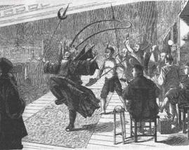
Figure 3. 19th century drawing of Beijing opera
Other interactive plays allow the audience to modify the course of actions in the performance of the play, and even allow the audience to participate in the performance as actors. Thus in these plays the audience has an active role. However, this does not mean that the readers of a novel or the members of audience in the theater are passive: they are quite active, but their activity remains internal.
The written text of the play is much less than the event of the play. It contains only the dialog (the words that the characters actually say), and some stage directions (the actions performed by the characters). The play as written by the playwright is merely a scenario which guides the director and actors. The phenomenon of theater is experienced in real-time. It is alive and ephemeral – unlike reading a play, experiencing a play in action is of the moment – here today, and gone tomorrow.
To prepare for the formalization in the next section, we fix some terms. The word performance is used to refer to the artifact the audience and the participants experience during the course of performing a script by preferred actors, monitored and instructed by a director. The script is the underlying content representation perceived by the authors as a composite unit, defining the temporal aspects of the performance, and containing the actions which are depicted by the content elements or the references to these elements. Traditional multimedia systems use a different set of terms which are comparable to the terms above; they are in many cases similar, but should not be confused.
In the next section we review the language elements of SMIL (Ayars et al., 2005), later taking them as a starting point for the design of our IPML, preserving the good ingredients and developing extensions that are necessary.
SMIL
Synchronized Multimedia Integration Language (SMIL) is an XML-based language for writing interactive multimedia presentations (Ayars et al., 2005). It has easy to use timing modules for synchronizing many different media types in a presentation. SMIL 2.0 has a set of markup modules.
Without attempting to list all the elements in these modules, we show an object-oriented view of some basic elements in Figure 4: Par, and Seq from the timing and synchronization module, Layout, RootLayout, TopLayout and Region from the layout module, Area from the linking module, MediaObject from the media object module, Meta from the meta information modules and Head, Body from the structure module. Details about the corresponding language elements can be found in the SMIL 2.0 specification (Ayars et al., 2005).
The Region element provides the basics for screen placement of visual media objects. The specific region element that refers to the whole presentation is the RootLayout.
Common attributes, methods and relations for these two elements are placed in the super-class named the Layout.
SMIL 2.0 introduces a MultiWindowLayout module over SMIL 1.0, with which the top level presentation region can also be declared with the TopLayout element in a manner similar to the SMIL 1.0 root-layout window, except that multiple instances of the TopLayout element may occur within a single Layout element.
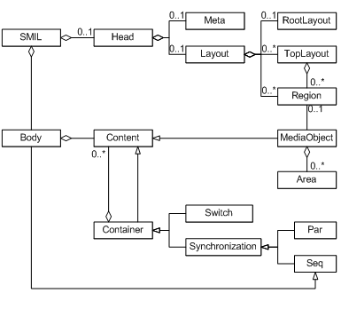
Figure 4. SMIL in UML
Each presentation can have Head and Body elements. In the Head element one can describe common data for the presentation as whole, such as Meta data and Layout. All Region elements are connected to the Head.
The MediaObject is the basic building block of a presentation. It can have its own intrinsic duration, for example if it is a video clip or an audio fragment. The media element needs not refer to a complete video file, but may be a part of it. The Content, Container, and Synchronization elements are classes introduced solely for a more detailed explanation of the semantics of the Par, Seq, Switch and MediaObject, and their mutual relations.
Par and Seq are synchronization elements for grouping more than one Content element. If the synchronization container is Par, it means that direct sub-elements can be presented simultaneously. If the synchronization container is Seq, it means that direct sub-elements can be presented only in sequence, one at a time. The Body element is also a Seq container.
The connection between Content and Container viewed as an aggregation has a different meaning for the Synchronization element and for the Switch element. If the Container element is Switch, which means that only one sub-element from a set of alternative elements should be chosen at the presentation time depending on the settings of the player.
With the Area element, a spatial portion of a visual object can be selected to trigger the appearance of the link’s destination. The Area element also provides for linking from non-spatial portions of the media object’s display. It allows breaking up an object into temporal subparts, using attributes begin and end.
IPML
SMIL seems to have the ingredients for mapping and timing:
- Its timing and synchronization module provides versatile means to describe the time dependencies, which can be directly used in the IPML design without any change.
- The SMIL linking module enables non-linear structures by linking to another part in the same script or to another script. Although the Area element can only be attached to visual objects, this limitation can be easily solved by lifting the concept up to a level that covers all elements that need to have a linking mechanism.
- The SMIL layout module seems to be very close to the need of distribution and mapping. The concept of separating mapping and timing issues into two different parts, i.e. Head and Body, makes SMIL very flexible for different layouts – if a presentation has to be presented to a different layout setting, only the layout part must be adapted and the timing relations remain intact, no matter whether this change happens before the presentation in authoring time, or during the presentation in run time.
Upon first investigation, SMIL appears not directly applicable for the distributed and interactive storytelling: it does not support a notion of multiple devices. However later we found that we went one step too far – the StoryML does incorporate the concept of multiple actors, but it is its linear timing model and narrative structure which limit its applicability.
What needs to be done is to pick up SMIL again as the basis for the design, extending it with the metaphor of theater play, and bringing in the lessons we learnt from StoryML. Figure 5 shows the final IPML extension (marked gray) to SMIL. The Document Type Definition (DTD) of IPML can be found in (Hu, 2006).
Note that in Figure 5, if all gray extensions are removed, the remaining structure is exactly the same as the SMIL structure as illustrated in figure 5. This is an intentional design decision: IPML is designed as an extension of SMIL without overriding any original SMIL components and features, so that the compatibility is maximized. Any SMIL script should be able to be presented by an IPML player without any change. An IPML script can also be presented by a SMIL player, although the extended elements will be silently ignored. The compatibility is important, because it can reduce the cost of designing and implementing a new IPML player – the industry may pick up the IPML design and build an IPML player on top of a existing SMIL player so that most of the technologies and implementations in the SMIL player can be reused.
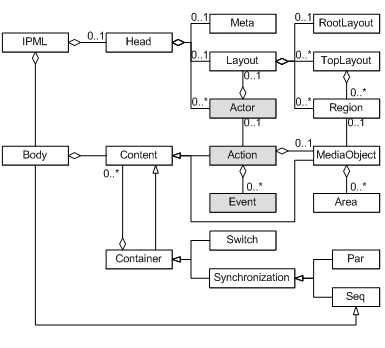
Figure 5. IPML in UML
Actor
The Head part of an IPML script may contain multiple Actor elements which describe the preferred cast of actors. Each Actor has a type attribute which defines the requirements of what this actor should be able to perform. The type attribute has a value of URI, which points to the definition of the actor type. Such a definition can be specified using for example RDF (McBride, 2004) and its extension OWL. RDF is a language for representing information about resources in the World Wide Web. It is particularly intended for representing metadata about Web resources. However, by generalizing the concept of a “Web resource”, RDF can also be used to represent information about things that can be identified on the Web, even when they cannot be directly retrieved on the Web. OWL adds more vocabulary for describing properties and classes: among others, relations between classes (e.g. disjointness), cardinality (e.g. “exactly one”), equality, richer typing of properties and characteristics of properties (e.g. symmetry), and enumerated classes. The “thing” we need to describe is the type of the actor.
During the performance time, the real actors present to the theater to form a real cast. Each actor then needs to report to the director about what he can perform, i.e. his actor “type”. The “type” of a real actor is defined by the actor manufacturers (well, if an actor can be manufactured). The real actor’s type can again be described using an RDF or OWL specification. The director then needs to find out which real actor fits the preferred type best. The mapping game becomes a task of reasoning about these two RDF or OWL described “types”. First of all the user’s preferences should be considered, even if the user prefers a “naughty boy” to perform a “gentleman”. Otherwise, a reasoning process should be conducted by the director, to see whether there is exactly an actor has a type that “equals to” the “gentleman”, or to find an “English man” that indeed always “is a” “gentleman”, or at least to find a “polite man” that “can be” a “gentleman” and that matches “better than” a “naughty boy”, etc. This reasoning process can be supported by a variety of Semantic Web (Berners-Lee & Fischetti, 1999) tools, such as Closed World Machine (CWM) (Berners-Lee, Hawke, & Connolly, 2004) and Jena (McBride, 2001) just for example.
Although Alice in Wonderland would be a difficult play to map, we can use it to illustrate some ideas again. For example, Alice could be played on several devices. But the Duchess is supposed to appear impressive and with dominance, so a close-up on a large screen serves that purpose best. The Frog preferably is active by playing with physical objects, so a robotic device would be best. Moreover, when played by a robot, it can jump and run around. One possible mapping, taking these simple constraints into account, is shown in Figure 6.
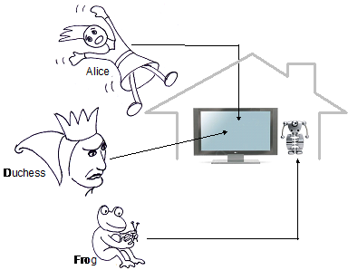
Figure 6. Mapping Alice and Duchess to large screen and Frog to robot
Action
The Action element is similar to the MediaObject element in SMIL. However, Action can be applied to any type of content element which is not explicitly defined using different media objects such as Img, Video and Animation in SMIL. The Action element has an attribute src giving the URI of the content element and its type either implicitly defined by the file name extension in the URI if there is one, or explicitly defined in another attribute type. The type attribute defines the type of a content element as the type attribute of Actor defines the actor type, using a URI referring to a definition.
Action may have an attribute actor to specify the preferred actor to perform it. If it is not specified, the type of the content element may also influence the actor mapping process: the director needs to decide which actor is the best candidate to perform this “type” of action. Again, the user preference should be taken into account first; otherwise a reasoning process should be conducted to find the “gentleman” who can nicely “open the door for the ladies”.
In addition, the Action element may have an observe attribute which specifies the interested events. This attribute is designed for an actor to observe the events that are of interest during the course of performing a specific action. For example, when an actor is performing an action to present a 3D object, it may be interested in the controlling events for rotating the object. This actor can then “observe” these events and react on it. Note that these observed events have no influence on the timing behavior. It will not start nor stop presenting this 3D object unless they are included in timing attributes, i.e., begin and end. Events that are not listed will not be passed by the director to the actor during this action, thus the event propagation overhead can be reduced.
However, some actors may be interested in the events that are not related to certain actions. To accommodate this and not to change the original SMIL structure, we require these Actors to perform an action of the type null, specified using a special URI scheme “null:”, which allows events to be “observed” during an action of “doing nothing”.
Event
The third extension of IPML to SMIL is event based linking using the Event element. Event elements in an Action element are similar to Area elements in a visual MediaObject element in SMIL, with the exceptions that it does not require the parent Action element to have a visual content to present, and that the events are not limited to the activation events (clicking on an image, for example) on visual objects. An Event has an attribute enable to include all interested events during an action, including all possible timing events and user interaction events. Once one of the specified events happens, the linking target specified using the attribute href is triggered. Similar to the Area element, the Event element may also have begin, end and dur attributes to activate the Event only during a specified interval. Event based linking makes IPML very flexible and powerful in constructing non-linear narratives, especially for the situations where the user interaction decides the narrative directions during the performance.
Again with Alice in Wonderland
To show what an IPML script would look like in practice, we again use the example from Alice in Wonderland. Since we can’t embed multimedia content elements in this printed paper and we only have printed lines and action instructions, we introduce two exotic URI schemes: “say:” for the lines and “do:” for the action instructions, just for the fun of it.
<ipml>
<head>
<actor id="ALICE" type="http://alice.wonderland.eu/lovelygirl" />
<actor id="DUCHESS" type="http://alice.wonderland.eu/seriouswoman" />
<actor id="COOK" type="http://alice.wonderland.eu/cook" />
<actor id="FROG" type="http://alice.wonderland.eu/frog" />
<actor id="HOUSE" type="http://alice.wonderland.eu/woodenhouse" />
</head>
<body>
<!----->
<action id="As_1" actor="ALICE" src="say:Please! Mind what you're doing!" />
<par>
<action id="Dd_2" actor="DUCHESS" src="do:tossing Alice the baby" />
<action id="Ds_2" actor="DUCHESS" src="say:Here...you may nurse it if you like, I've got to get
ready to play croquet with the Queen in the garden." />
<action id="Ad_2" actor="ALICE" src="do:receiving the baby" begin="Dd_2.babytossed"/>
</par>
<action id="Dd_3" actor="DUCHESS" src="do:turns at the door" />
<action id="Ds_3" actor="DUCHESS" src="say:Bring in the soup." />
<!----->
<par>
<action actor="HOUSE" src="do:moving" />
<seq>
<par>
<action actor="DUCHESS" src="say:The house will be going any minute!" />
<action actor="COOK" src="do:snatches up her pot and dashes into the house" />
</par>
<action actor="COOK" src="do:turns to the FROG" />
<action actor="COOK" src="say:Tidy up, and catch us!"
<par>
<action actor="FROG" src="do:leaps about" />
<action actor="FROG" src="do:picking up the vegetables, plates, etc." />
<action actor="ALICE" src="say:She said 'in the garden', will you please tell me -" />
</par>
<action actor="FROG" src="say:There's no sort of reason asking me,
I'm not in the mood to talk about gardens." />
<action actor="ALICE" src="say:I must ask some one.
What sort of people live around here?" />
</seq>
</par>
</body>
</ipml>
Now that we have a scripting language that can be used for describing a distributed presentation, a playback system is needed to turn a written “play” to a performance. Next the structure of such a playback system is presented.
ACTORS: DISTRIBUTED PAC AGENTS
The actors are in the system not only to perform their actions to present the multimedia objects, but also to provide the interface for the users to interact with the system. Many interactive architecture structures have been developed along the lines of the object-oriented and the event driven paradigms. Model-View-Controller (MVC) (Krasner & Pope, 1988) and Presentation-Abstraction-Control (PAC) (Coutaz, 1987) are the most popular and often used ones (Buschmann, Meunier, Rohnert, Sommerlad, & Stal, 1996).
The MVC model divides an interactive agent into three components: model, view and controller, which respectively denotes processing, output and input. The model component encapsulates core data and functionality. View components display information to the user. A View obtains the data from the model. There can be multiple views, each of which has an associated controller component. Controllers receive input, usually as events that encode hardware signals from input devices.
Coutaz (1987) proposed a structure called Presentation-Abstraction-Control, which maps roughly to the notions of View-Controller pair, Model, and the Mediator pattern (Gamma, Helm, Johnson, & Vlissides, 1995). It is referenced and organized in a pattern form by Buschmann et al. (1996): the PAC pattern “defines a structure for interactive software systems in the form of a hierarchy of cooperating agents. Every agent is responsible for a specific aspect of the application’s functionality and consists of three components: presentation, abstraction, and control. This subdivision separates the human-computer interaction of the agent from its functional core and its communication with other agents.”
In the design of the IPML player, PAC is selected as the overall system architecture, and the actors are implemented as PAC agents that are managed by the scheduling and mapping agents in a PAC hierarchy, connected with the channels, and performing the actions. Hu (2006) argues in detail why PAC is preferred to MVC for the IPML player.
Distributed PAC
This structure separates the user interface from the application logic and data with both top-down and bottom-up approaches (Figure 7). The entire system is regarded as a top-level agent and it is first decomposed into three components: an Abstraction component that defines the system function core and maintains the system data repository, a Presentation component that presents the system level interface to the user and accepts the user input, and in between, a Control component that mediates the abstract component and the presentation component. All the communications among them have to be done through the control components.
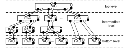
Figure 7. Distributed PAC in a hierarchy
At the bottom-level of a PAC architecture are the smallest self-contained units which the user can interact with and perform operations on. Such a unit maintains its local states with its own Abstraction component, and presents its own state and certain aspects of the system state with a Presentation component. The communication between the presentation and the abstraction components is again through a dedicated Control component.
Between the top-level and bottom level agents are intermediate-level agents. These agents combine or coordinate lower level agents, for example, arranging them into a certain layout, or synchronizing their presentations if they are about the same data. The intermediate-level may also have its interface Presentation to allow the user to operate the combination and coordination, and have an Abstraction component to maintain the state of these operations. Again, with the same structure, there is a control component in between to mediate the presentation and the abstraction.
The entire system is then built up as a PAC hierarchy: the higher-level agents coordinate the lower level agents through their Control components; the lower level agents provide input and get the state information and data from the higher level agents again through the Control components. This approach is believed more suitable for distributed applications and has better stability than MVC, and it has been used in many distributed systems and applications, such as CSCW (Calvary, Coutaz, & Nigay, 1997), distributed real-time systems (Niemelä & Marjeta, 1998) , web-based applications (Illmann, Weber, Martens, & Seitz, 2000; Zhao & Kearney, 2003), mobile robotics (Khamis, Rivero, Rodriguez, & Salichs, 2003; Khamis, Rodriguez, & Salichs, 2003), distributed co-design platforms (Fougeres, 2004) and wireless services (Niemelä, Kalaoja, & Lago, 2005).
To a large degree the PAC agents are self-contained. The user interface component (Presentation), the processing logic (Abstraction) and the component for communication and mediation (Control) are tightly coupled together, acting as one. Separations of these components are possible, but these distributed components would then be regarded as PAC agents completed with minimum implementation of the missing parts. Thus the distribution boundaries remain only among the PAC agents instead of composing components.
Based on this observation, each component is formally described by Hu (2006), modeling the communication among PAC agents with push style channels from the Channel pattern. In Figure 1, a “●” indicates a data supplier component; a “○” indicates a data consumer component and a connecting line in between indicate the channel. The symbol “■” indicates that the attaching component has a function of physically presenting data to the user, and the symbol “□” indicates the function of capturing input from the user interface or the environment.
Actor: A PAC Agent
After this detailed comparison with MVC we are ready to harvest the fruits of the PAC style: the PAC agents are perfectly suited to implement the notion of “play”, that is, the central notion in IPML scripts.
An actor is basically a PAC agent. It reacts on the user input events and scheduling commands, and takes actions to present media objects. Hu (2006) describes an example implementation of an actor based on the Distributed PAC pattern and other patterns including Synchronizable Object, Channel and Action described therein.
IPML Player: An IPML Actor
The final IPML system is simply an IPML actor, or in other words, an Actor implementation that is capable of presenting the IPML scripts. IPML is a presentation description language that extends SMIL, describing the temporal and spatial relations among distributed actions on synchronizable content elements.
Note that IPML is an extension of SMIL, and a SMIL document is actually a composite content element by itself. Hence an IPML actor is first of all a SMIL player and it may present the contained content elements to its own Presentation component. What makes IPML superior to a SMIL player is the capability of distributed presentation, interaction and synchronization: It can delegate content presentations to other actors, synchronize the presentation actions of these actors, and propagate distributed user interaction events among these actors.
The IPML actor implements the role of a Director, which has a mapping engine, creates, manages and connects the virtual actors, and has a timing engine which schedules the timed actions for the delegating virtual actors (Figure 8). Depending on the physical configuration of the “theater” – the presenting environment, the mapping engine may also connect appropriate “real actors” to virtual actors, where the virtual actors keep the role of software drivers for the “real actors”. The mapping engine may make use of distributed lookup and registration services such as UPNP (Michael Jeronimo, 2003) and JINI (Edwards, 2000) to locate and maintain a list of “real actors”, but this architecture leaves these possibilities open to the implementation of the mapping engine.
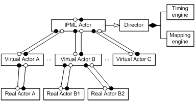
Figure 8. IPML system: an IPML actor
The timing and mapping engines are essential parts of the system. In the flowing two sections they are presented in more detail.
ACTION SYNCHRONIZATION ENGINE
An interactive play has been defined as a cooperative activity of multiple actors that take actions during certain periods of time to present content elements. An action, as the basic component of such an activity, has a time aspect per se. That is, a timing mechanism is needed to decide when the actor should commence the action, how long the action should take, and how the actions are related to each other in time.
IPML has been presented as the scripting language, in which the SMIL timing model is used for describing the time relations between actions. A runtime synchronization engine is presented here. It provides a powerful, flexible and extensible framework for synchronizing the actions. This engine is used by the director to schedule the actions for the actors, no matter whether the actors are distributed over the network.
ASE Model
ASE is a runtime Action Synchronization Engine that takes the timing and synchronization relations defined in an IPML script as input, and creates an object-oriented representation based on an extended version of the Object Composition Petri Net (OCPN) (Little & Ghafoor, 1990).
An ASE model is a nine tuple that extends OCPN,

where,
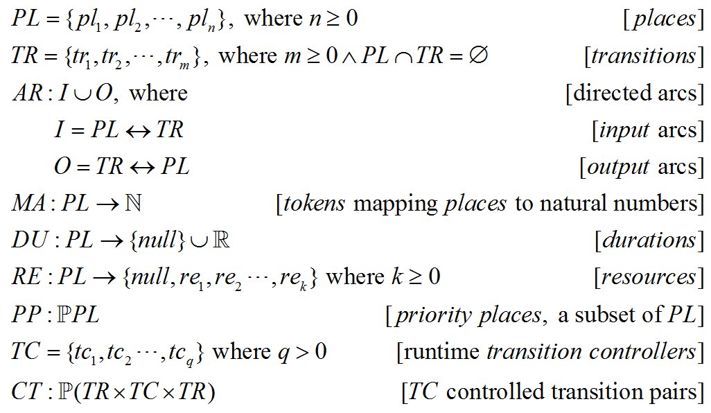
The behavior of the Petri net is governed by a set of firing rules that allows the tokens to move from one place to another. The inclusion of a null value in the ranges of the functions DU and RE means that there are places without a pre-determined duration, and there are places not related to any content resources.
The ASE model distinguishes priority places from other places. Special firing rules will be used for these priority places to implement the IPML endsync semantics and to cope with nondeterministic durations and interaction events. A priority place is drawn as a circle in an ASE graph like other places, but using a special (thicker) circle to emphasize its priority.
The added transition controllers TC make it possible to change the structure between two transitions in run time. It may fire another linked transition instead of the current enabled transition, which can be used to repeat or skip the structure between the controlled transition pairs. The controller may use a counter to control the number of repeat iterations, and may add and remove timer places in the structure to control the total duration for repeat. This mechanism is useful when dealing with IPML restart, repeatCount and repeatDur semantics. In an ASE graph, a box represents a transition controller, and dashed lines connect the controlled transition pairs (Figure 9).
As already mentioned, there are places that do not have a pre-determined duration. The actual duration of these places can only be determined after the actions at these places have been carried out. These places are called nondeterministic places:

Non-deterministic places in an ASE graph are circles marked with a question mark.
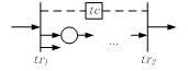
Figure 9. Transition controller
Some nondeterministic places are not related to any content resources. These places are used in an ASE model to represent the actions that need to be taken by the engine itself to check certain conditions, to detect user interaction events, or simply to block the process etc. These places are called auxiliary places:

There are also places that do have duration, but do not have a content element attached to it. These places are used by the ASE model to include an arbitrary interval to construct temporal relations. These places are called timer places:

Timer places are indicated with a clock icon with the hands pointing to 9:00am. To construct an ASE graph from an IPML script structurally, it is sometimes necessary to connect two transitions. Since an arc can only be the link between a transition and a place, a zero-duration timer place can be inserted to maintain the consistency. These zero-duration timer places are called connecting places, indicated with a clock icon with its hands pointing to 0:00pm, and marked with an anchor link.
Table 1. Places in ASE
Place |
Normal |
Priority |
Normal |
|
|
Nondeterministic |
|
|
Timer |
|
|
Connecting |
|
|
Table 1 shows the graph representations of the different ASE places and their priority versions. To show how an ASE would look like, the example of Alice in Wonderland is again used. The script fragment between two “<!---->” lines in the example given in the section “Again with Alice in Wonderland” are converted to a temporal structure as shown in Figure 1. The connecting places are not visible in this structure, but they are essential in the process of converting an IPML script to an ASE model. Every temporal element in an IPML is firstly formally mapped to an ASE model that utilizes connecting places. The purpose is to keep it always possible to embed sub-models into this model, which corresponds to the hierarchical temporal structure of the IPML elements. After the entire IPML is converted, the connecting places in the model are removed whenever it is possible to simplify the final ASE model.
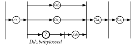
Figure 10. An example of the ASE model
The firing rules of ASE and the formal process of translating an IPML script into a simplified ASE model are described by Hu (2006). More comprehensive examples are also given therein.
Object-oriented Implementation of ASE
The ASE in the IPML system is implemented in an object-oriented manner (Figure 11): Places and transitions are objects with input and output references that realize the arcs; transition enabling and firing are simply event-driven invocations. The Observer pattern can be used to implement the structure, where the transitions observe the token states of the connected places. Transition controllers are also objects with references to and from two related transitions. If the different types of the places are omitted from Figure 11, the remaining static structure is rather simple. The dynamic behavior of these objects is driven by the firing rules and the implementation of the dynamic behavior is straightforward. The remaining design problem now is how to convert an IPML timing structure to an ASE model.
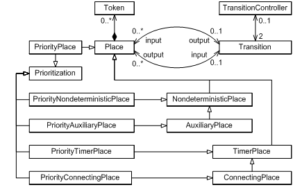
Figure 11. Object-oriented implementation of ASE
Get Ready Just-in-time
For an action to be immediately taken at the scheduled time, actors need to get ready prior to that time. For media objects, enough data needs to be prefetched; For robotic behaviors the mechanical system needs to be at a ready position for the next move. Two extreme strategies could be adopted by the director. First, the director informs all actors to get prepared for all possible actions before the performance is started; second, the director never requests the actor to get ready before any action. The first strategy guarantees the smooth transitions between actions, and manages nondeterministic timing and user interaction well. However the cost is also obvious: it may result in a long initial delay and for media objects, and every actor needs a large buffer for prefetching all media objects in advance. The second strategy minimizes the initial start delay and the buffer requirement, but every transition between two actions will take time because the next action only starts to be prepared after the previous one stops. Hence smooth transitions between action places are not possible, unless the actions do not need to be prepared, which is rare in multimedia presentations. The nondeterministic user interactions make the situation even worse – Users may experience a long delay between their input actions and the system reactions. A different approach is needed for the IPML system.
Just-in-time approach. The director in the IPML system uses a “just-in-time” approach, in which the action preparation process is required to be completed just before the action time. With this strategy, the director informs the actor to prepare an action before the action time with the necessary preparation time taken into account. This strategy therefore requires less use of data buffers and facilitates more efficient use of network bandwidth.
In an ideal situation, i.e. the action time of all actions can be determined in advance, the start-preparation time for each action, that is, when an actor should start preparing an action, can be calculated based on its playback time, its QOS request, and the estimation of the available network bandwidth.
However for an IPML performance, the accurate action time often can not be determined before the performance takes place, because of the nondeterministic action durations and user interaction events. The best an ASE can do is to predict the earliest action time for each action as if the non-mechanistic events would happen at the earliest possible moments. This can be done before the performance starts, as long as the ASE model has been established. During the performance, a dynamic error compensation mechanism can be used to adjust the estimate of the action time for each action and the start-reparation time as well.
Action time prediction. Once an ASE is converted and simplified from a given IPML, the director estimates the earliest possible action time for each action in the ASE by first assigning the duration of all nondeterministic places to zero and then traversing the ASE. The action time of an action is the firing time of its starting transition. There are two possible cases for a transition in the ASE: 1. it has no priority input place, or 2. it has at least one priority input place. For case 1, the firing time of the transition is the firing time of the preceding transition plus the maximum duration of the input places. For case 2, the firing time of the transition is instead the preceding transition plus the smaller one between the minimum duration of the priority places, and the maximum duration of the non priority places. Note that for time independent actions, such as presenting images and text, if the duration is not explicitly given, it is considered nondeterministic and its duration is considered as zero for prediction. For time-dependent actions, like presenting audio and video media objects, if the duration is not defined explicitly, the duration of the place is the implicit duration of the object if it can be determined from the server in advance.
During this traversal process of predicting the earliest possible firing time of each transition, it is also necessary to deal with the transition controllers to get more accurate values. The restart controller deals with events that could restart an element during the active duration of the element, so the earliest case for its ending transition would be that there is no restart at all. Thus, the restart controller is ignored during prediction. The repeat controller deals with the repeatDur attribute as well as the repeatCount attribute. The repeatDur attribute sets the duration of repeating an element, so the firing time of the ending transition should be the end of the repeat duration. The repeatCount attribute specifies the number of times to repeat, thus the firing time of the ending transition is extended as many times as specified. If any of them is set to be “indefinite”, the duration is considered nondeterministic hence a value of zero.
Dynamic adjustment. Obviously, the actual action time of every action will not be earlier than the prediction made prior to the performance. The differences between the actual action time of the actions that have already been taken and their predicted earliest times can be used to adjust the predicted action time of the actions that have not yet been performed. The predicted action time can then be updated for those yet to happen. The updated prediction of the action time can then be used to update the start-preparation time. Note that start-preparation time should not be updated if the preparation request has already been sent to the actor, since the actor may have already started preparation and an ongoing preparation process should not be interrupted. Nevertheless an ASE action time prediction with this dynamic adjustment mechanism does make the predicted action time of later actions closer to the actual action time, hence seems more intelligent than without.
Distributed time
Since they inhabit on different hardware platforms, actors may have time systems that are different from the directors. In order to get everything synchronized, the actors must use the director’s time, or at least agree on the time difference. A simple approach to get actors have the same time as the director’s, is to use clock synchronization mechanisms to synchronize the clocks of the underlying platforms.
Clock synchronization. An actor may perceive data skews due to asynchrony of its local clock with respect to the clock of the director, which may arise due to network delays and/or drifts in the clocks. In the absence of synchronized clocks, the time interval of an actor may have drifted to a value bigger or smaller than that of the director.
Clocks can be synchronized using an asynchronous protocol between the transport level entities in the presence of network delays compounded by clock drifts. Most clock synchronization protocols require the entities to asynchronously exchange their local clock values through the network and agree on a common clock value. These protocols use knowledge of the network delays in reaching agreement. For instance, the NTP requires the entities to receive their clock values from a central time server that maintains a highly stable and accurate clock and to correct the received clock values by offsetting the network delays. For clock synchronization protocols to function correctly, it is desirable that the network delay is deterministic, i.e., the degree of randomness in the delay is small and the average delay does not change significantly during execution of synchronization protocol. Accordingly, the transport protocol may create a deterministic channel with high loss and delay sensitivity to exchange clock control information. Clock synchronization is a complex topic of its own, and details of such protocols are outside the scope of this paper.
Software clocks. The actors are not the only ones who inhabit a hardware platform. There may be other hardware or software components sharing the same platform clock. Applying clock synchronization mechanisms to the shared clock may result in unexpected consequences on the components that are not under the supervision of the play director but have other time critical tasks of their own.
To avoid this side effect, the IPML system requires every actor to implement a software clock. The actor’s clock is then synchronized with the director’s clock using NTP according to the director’s time on a regular interval basis. During the update interval, the actor’s clock ticks ahead according to the local platform time.
“Action!” delayed. The director issues action scheduling commands over the network to the actors. “Action!” the director yells and expects the actor immediately starts the action. In real performance, these directing commands travel at the speed of sound and will be heard by the actor almost “immediately”. However in the IPML system, these commands are not the only data traveling through the network. A command may need to be cut into pieces, packaged and queued at the director’s side waiting for the network service to move it over. Once the packages arrive at the actor’s side, they are again put in the queue for the network service to retrieve them. Once retrieved, depending on the network protocol, the data packages might need to be verified and confirmed before the command is reassembled and handed over to the actor. All these take time. Depending on the protocol and the bandwidth, it varies from few milliseconds to hundreds of milliseconds, or even more. The command will eventually be heard late. Since a particular network protocol is not assumed for transporting the commands, it is necessary to handle the delay at the architecture level.
Several strategies are adopted in the IPML system. First of all, all scheduling commands from the director are tagged with a time stamp that indicates when exactly the command is issued. Upon receipt, the actor retrieves the time stamp and compares it to its local software clock. Since the actor’s clock is synchronized with the director’s clock, the traveling time of the command can be calculated. If the command is not to start an action to present time-dependent content, the traveling time of the command is ignored. Otherwise if the traveling time is bigger than a QOS threshold, the actor will skip a fragment of time-dependent content that should have been performed right after the command was issued and before the command is received. Thus the distributed content elements can always be synchronized over the network, at the price of a small portion of the content being dropped at the beginning. If the network has enough bandwidth, the dropped content is hardly noticeable by the user.
IPML MAPPING
As learnt from the formal study on the mapping issues (Feijs & Hu, 2004), a mapping process is a set of controlling commands, to be sent through control channels to the components that are capable of copying and combining streams from input channels to output channels. All the actors in the IPML system are all connected through channels in a PAC hierarchy and controlling commands can be sent though these connecting channels. How the mapping can be handled in a dynamic setting is briefly described next.
Virtual Actors
Virtual actors are required in the IPML system architecture (Figure 8) as an essential layer of software PAC agents for dynamic mapping. These agents can be provided by the vendors of the real actors as a software driver, or by the content producers as a “recommended” actor if there is no real actor available. These virtual actors can be provided by an installation package which requires the user to install it in advance, or for example an Internet resource identified by a URL such that the virtual actor can be downloaded and installed automatically. Here one shall not try to cover the security and privacy consequences of this automatic downloading and installation process, since it has been an issue for all Internet applications and should be taken care of by dedicated protocols and subsystems.
Once the virtual actors are available to the IPML system, it is then registered and maintained by the mapping engine of the director.
Channel Resources
The system also provides and maintains a distributed channel service over the connected devices. Here it benefits from the design of the channel patterns (Hu, 2006): all channels between actors and the director are distributed objects managed by a channel service, hence the network resources can be easily monitored and allocated with QOS and load balancing taken into account. The director may query the channel service so that the communication conditions can be taken into account during the mapping process.
Mapping heuristics
The IPML director has a list of available virtual actors together with their types given. The director also has access to the channel service to query the channel resources to find out whether a virtual actor is connected to a real actor. Given an actor type as the requirement, the IPML uses the following heuristics to map the required actor type to a virtual actor:
- The user preference has top priority.
- If after 1 multiple virtual actors can be selected, the ones having the “closest” type have the priority over the others.
- If after 2 multiple virtual actors can be selected, the
ones with a real actor
connection have priority over those without. - If after 3 multiple virtual actors can be selected, the one that has been selected most recently for this type is again selected. If none of them have ever been selected, the director randomly selects one from these virtual actors.
- If none of the virtual actors can be selected, the director creates a “dummy” virtual actor for this type. The “dummy” virtual actor will do nothing but ignore all requests.
In step 2, how to decide an actor is the “closest” to another among the others is not clearly described. It depends on how the types are defined. In practice, one may leave it to an ontology reasoning system for example a semantic web tool for RDF or OWL type descriptions.
During the action time, these heuristic conditions may change, for example, the real actors may connect and disconnect from the “theater” at any time, and users may change their minds at any time to have a “gentleman” instead of a “naughty boy” to be the actor or vice versa. To dynamically update the mapping relations, the director needs to repeat this mapping process on a regular interval basis.
Actor/director Discovery
The problem now is how the virtual actors, the real actors and the director can find each other for registration and connection. This is actually a well-known device/service discovery problem and many middleware standards (for example JINI, HAVI, OSGi and UPnP) have a solution for it. So one may simply leave the discovery task of registering virtual actors to the director, and leave the task of connecting virtual actors and the real actors to these middleware infrastructures.
CONCLUSIONS
On top of existing network technologies and platform architectures, a generic architecture has been designed to enable playing IPML in a networked environment with user preference and dynamic configurations taken into account. The architecture has been implemented and tested in Java, and several demonstrators have been built upon this architecture (Feijs & Hu, 2004; Hu & Bartneck, 2005; Hu & Feijs, 2003; Hu, Janse, & Kong, 2005; Janse, van der Stok, & Hu, 2005). It has been applied in various projects, from big projects funded by the Information Society Technologies program of the European Commission (NexTV, IST-1999-11288; ICE-CREAM, IST-2000-28298), to small educational projects at the Department of Industrial design, Eindhoven University of Technology. The users of the architecture range from the professionals inside Philips Research, to undergraduate industrial design students.
In this design, the metaphor of play was an essential design decision. The scripting language and the architecture of the playback system are designed around this metaphor. The concept of mapping and timing are well covered in the architecture and proven to be easily understandable by both the system designers and the scriptwriters. In this era of digitalization, this might be yet another example that we still have much to learn from the traditional arts such as play.
REFERENCES
Aarts, E. (2004). Ambient intelligence: a multimedia perspective. IEEE Multimedia, 11(1), 12-19.
Ayars, J., Bulterman, D., Cohen, A., Day, K., Hodge, E., Hoschka, P., et al. (2005). Synchronized Multimedia Integration Language (SMIL 2.0) - [Second Edition] (W3C Recommendation).
Battista, S., Casalino, F., & Lande, C. (1999). MPEG-4: A Multimedia Standard for the Third Millennium, Part 1. IEEE MultiMedia, 6(4), 74-83.
Battista, S., Casalino, F., & Lande, C. (2000). MPEG-4: A Multimedia Standard for the Third Millennium, Part 2. IEEE MultiMedia, 7(1), 76-84.
Berners-Lee, T., & Fischetti, M. (1999). Weaving the Web: The Original Design and Ultimate Destiny of the World Wide Web by Its Inventor: Harper San Francisco.
Berners-Lee, T., Hawke, S., & Connolly, D. (2004). Semantic Web Tutorial Using N3 (Turorial).
Buschmann, F., Meunier, R., Rohnert, H., Sommerlad, P., & Stal, M. (1996). Pattern-Oriented Software Architecture, Volume 1: A System of Patterns: John Wiley & Sons, Inc.
Calvary, G., Coutaz, J., & Nigay, L. (1997). From single-user architectural design to PAC*: a generic software architecture model for CSCW. CHI'97 Conference, 242-249.
Carroll, L., & Chorpenning, C. B. (1958). Alice in Wonderland: Dramatic Publishing Co., Woodstock.
Coutaz, J. (1987). PAC, an Implemention Model for Dialog Design. Interact'87, 431-436.
Edwards, W. K. (2000). Core JINI: Prentice Hall PTR.
El-Nasr, M. S., & Vasilakos, T. (2006). DigitalBeing: An Ambient Intelligent Dance Space. Fuzzy Systems, 2006 IEEE International Conference on, 907-914.
Feijs, L. M. G., & Hu, J. (2004). Component-wise Mapping of Media-needs to a Distributed Presentation Environment. The 28th Annual International Computer Software and Applications Conference (COMPSAC 2004), 250-257.
Fougeres, A.-J. (2004). Agents to cooperate in distributed design. IEEE International Conference on Systems, Man and Cybernetics, 3, 2629-2634.
Gamma, E., Helm, R., Johnson, R., & Vlissides, J. (1995). Design Patterns - Elements of Reusable Object-oriented Software: Addison-Wesley.
Heckel, P. (1991). The Elements of Friendly Software Design.
Hu, J. (2003). StoryML: Enabling Distributed Interfaces for Interactive Media. The Twelfth International World Wide Web Conference.
Hu, J. (2006). Design of a Distributed Architecture for Enriching Media Experience in Home Theaters: Technische Universiteit Eindhoven.
Hu, J., & Bartneck, C. (2005). Culture Matters - A Study on Presence in an Interactive Movie. PRESENCE 2005, The 8th Annual International Workshop on Presence, 153-159.
Hu, J., & Feijs, L. M. G. (2003). An Adaptive Architecture for Presenting Interactive Media onto Distributed Interfaces. The 21st IASTED International Conference on Applied Informatics (AI 2003), 899-904.
Hu, J., Janse, M. D., & Kong, H. (2005). User Evaluation on a Distributed Interactive Movie. HCI International 2005, 3 - Human-Computer Interfaces: Concepts, New Ideas, Better Usability, and Applications, 735.731-710.
Illmann, T., Weber, M., Martens, A., & Seitz, A. (2000). A Pattern-Oriented Design of a Web-Based and Case Oriented Multimedia Training System in Medicine. The 4th World Conference on Integrated Design and Process Technology.
Janse, M. D., van der Stok, P., & Hu, J. (2005). Distributing Multimedia Elements to Multiple Networked Devices. User Experience Design for Pervasive Computing, Pervasive 2005.
Khamis, A., Rivero, D. M., Rodriguez, F., & Salichs, M. (2003). Pattern-based Architecture for Building Mobile Robotics Remote Laboratories. IEEE International Conference on Robotics and Automation (ICRA'03), 3, 3284-3289.
Khamis, A., Rodriguez, F. J., & Salichs, M. A. (2003). Remote Interaction with Mobile Robots. Autonomous Robots, 15(3).
Krasner, G. E., & Pope, S. T. (1988). A cookbook for using the model-view controller user interface paradigm in Smalltalk-80. Journal of Object Oriented Program, 1(3), 26-49.
Little, T. D. C., & Ghafoor, A. (1990). Synchronization and Storage Models for Multimedia Objects. IEEE Journal on Selected Areas in Communications, 8(3), 413-427.
McBride, B. (2001). Jena: Implementing the RDF Model and Syntax Specification. Semantic Web Workshop, WWW2001.
McBride, B. (2004). RDF Primer (W3C Recommendation).
Michael Jeronimo, J. W. (2003). UPnP Design by Example: A Software Developer's Guide to Universal Plug and Play: Intel Press.
Niemelä, E., Kalaoja, J., & Lago, P. (2005). Toward an Architectural Knowledge Base for Wireless Service Engineering. IEEE Transaction on Software Engineering, 31(5), 361-379.
Niemelä, E., & Marjeta, J. (1998). Dynamic Configuration of Distributed Software Components. ECOOP '98: Workshop ion on Object-Oriented Technology, 149-150.
Rutledge, L. (2001). SMIL 2.0: XML for Web Multimedia. IEEE Internet Computing, 5(5), 78-84.
Wang, Y. (2006). Cognitive Informatics: Towards Future Generation Computers that Think and Feel. structure, 16, 18.
Wang, Y. (2007). The Theoretical Framework of Cognitive Informatics. International Journal of Cognitive Informatics and Natural Intelligence, 1(1), 1-27.
Zhao, W., & Kearney, D. (2003). Deriving Architectures of Web-Based Applications. Lecture Notes in Computer Science, 2642, 301-312.
